- English
- Español
- Português
- русский
- Français
- 日本語
- Deutsch
- tiếng Việt
- Italiano
- Nederlands
- ภาษาไทย
- Polski
- 한국어
- Svenska
- magyar
- Malay
- বাংলা ভাষার
- Dansk
- Suomi
- हिन्दी
- Pilipino
- Türkçe
- Gaeilge
- العربية
- Indonesia
- Norsk
- تمل
- český
- ελληνικά
- український
- Javanese
- فارسی
- தமிழ்
- తెలుగు
- नेपाली
- Burmese
- български
- ລາວ
- Latine
- Қазақша
- Euskal
- Azərbaycan
- Slovenský jazyk
- Македонски
- Lietuvos
- Eesti Keel
- Română
- Slovenski
- मराठी
- Srpski језик

Wiring Methods of 1P/2P/3P/4P DC Circuit Breakers in UPS Power Supply Systems
In the configuration of UPS power supply systems, DC circuit breakers perform the dual functions of isolation and overcurrent protection for battery circuits. Different types of UPS power supplies correspond to different battery rated voltages and currents, thus requiring the adaptation of DC circuit breakers with different pole counts. This article will detail the various wiring methods of 1P/2P/3P/4P DC circuit breakers applied in UPS systems.
1. Circuit breakers have standard parameters including rated voltage and rated current (for 1P types). When these parameters fail to meet the battery’s voltage and current requirements, the operating voltage and current can be increased by adding the number of circuit breaker poles and adopting series-parallel connection configurations. Specifically, series connection increases the voltage while parallel connection increases the current. Here, we take a rated voltage of 250V as an example.
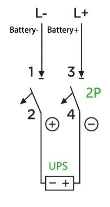
A: For example: For a UPS with a capacity of 40 kVA and a rated battery string of 32 cells (equalizing charge voltage: 14 V × 32 = 448 V; there are also batteries with a float charge voltage of only 13.6 V, which is used here for illustration purposes only), the maximum operating current is calculated as 40 kVA × 1.0 ÷ 90% ÷ 10 V ÷ 32 = 139 A (assuming a power factor of 1.0, an efficiency of 90%, and a UPS-set cut-off voltage of 10 V per cell). In this case, a 2P 500 V 200 A circuit breaker is sufficient. The wiring method is as follows:
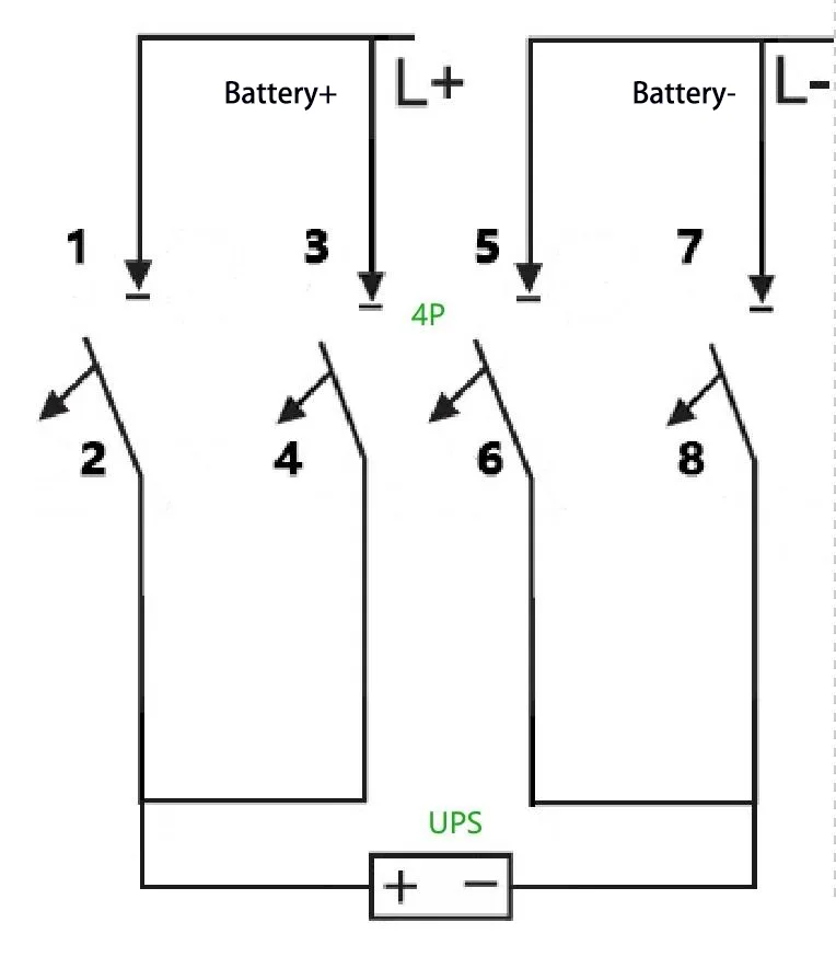
B: What if a 2P 500 V 100 A circuit breaker is used instead? This requirement can be fulfilled with a 4P circuit breaker—specifically, by paralleling two sets of 2P circuit breakers to enhance the current-carrying capacity. The wiring method is as follows:
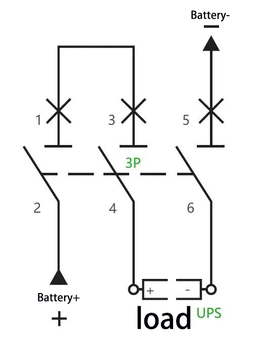
C: For example: For a UPS with a capacity of 40 kVA and a rated battery string of 40 cells (equalizing charge voltage: 14 V × 40 = 560 V), the maximum operating current is calculated as 40 kVA × 1.0 ÷ 90% ÷ 10 V ÷ 40 = 111 A. A 3P 750 V 150 A circuit breaker can be adopted, with two of its poles connected in series. The wiring method is as follows:
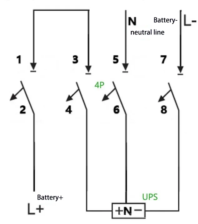
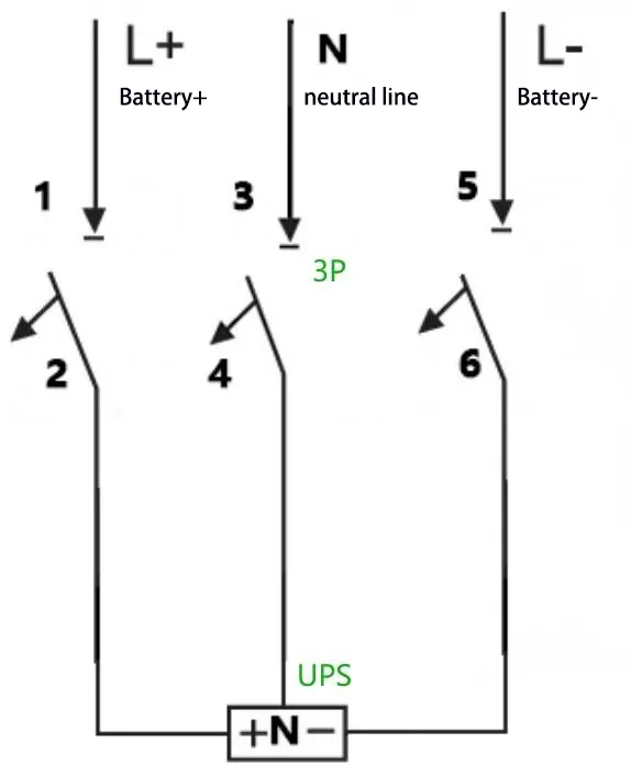
D: For example: For a UPS with a capacity of 40 kVA, a rated battery string of 32 cells, and neutral wire connection (equalizing charge voltage: 14 V × 32 = 448 V, i.e., ±224 V), the maximum operating current is calculated as 40 kVA × 1.0 ÷ 90% ÷ 10 V ÷ 32 = 139 A. A 3P 500 V 200 A circuit breaker can be adopted, and the wiring method is as follows:
E: For example: For a UPS with a capacity of 40 kVA, a rated battery string of 40 cells, and neutral wire connection (equalizing charge voltage: 14 V × 40 = 560 V, i.e., ±280 V), the maximum operating current is calculated as 40 kVA × 1.0 ÷ 90% ÷ 10 V ÷ 40 = 111 A. A 4P 750 V 150 A circuit breaker can be adopted, with two of its poles connected in series. The wiring method is as follows: